Upgrading a BitHead, Part II: Microphone input
Recently, at work, we moved to a new building that has even lower cube walls than before. And, to make matters worse, they took away our desk phones, with the expectation of using softphones from now on! This is something of a problem, I found, because I don't have a headset at work: my music listening setup was a pair of Shure SE215s, along with a HeadRoom BitHead amp. (You might remember that amp from a few years ago, when I upgraded it with new op-amps and noise filters.) It was neither the case that my SE215s had a microphone, nor that the BitHead amp had a circuit to deal with a microphone. So I did the only logical thing: I picked up a pair of q-JAYS (which I had been waiting for an excuse to do for a while), and decided to mod the BitHead to accept a microphone input.
Here's about how it went.
November - December 2017
Joshua Wise; CC BY-SA 3.0
(comments over on DreamWidth)
(click for big)
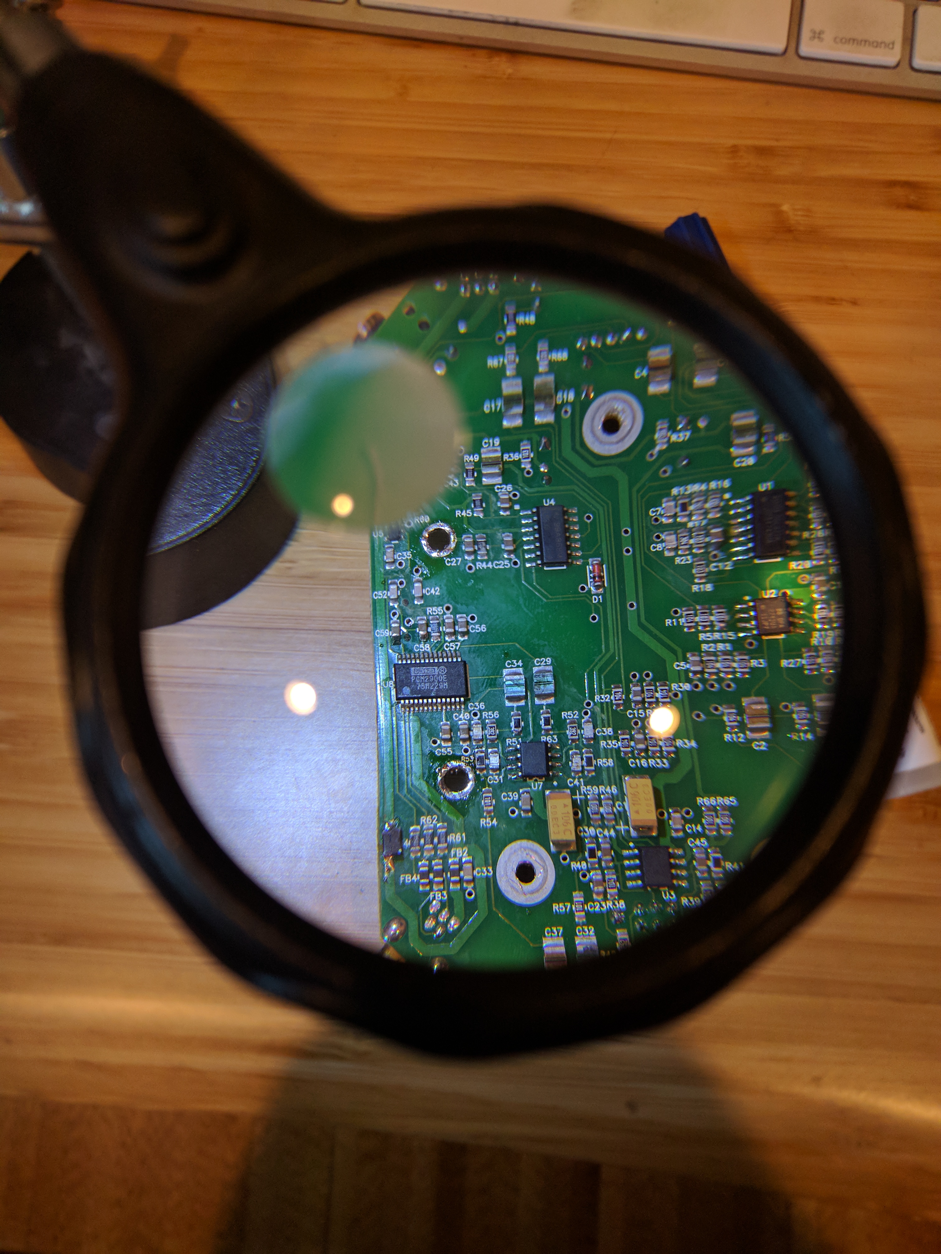
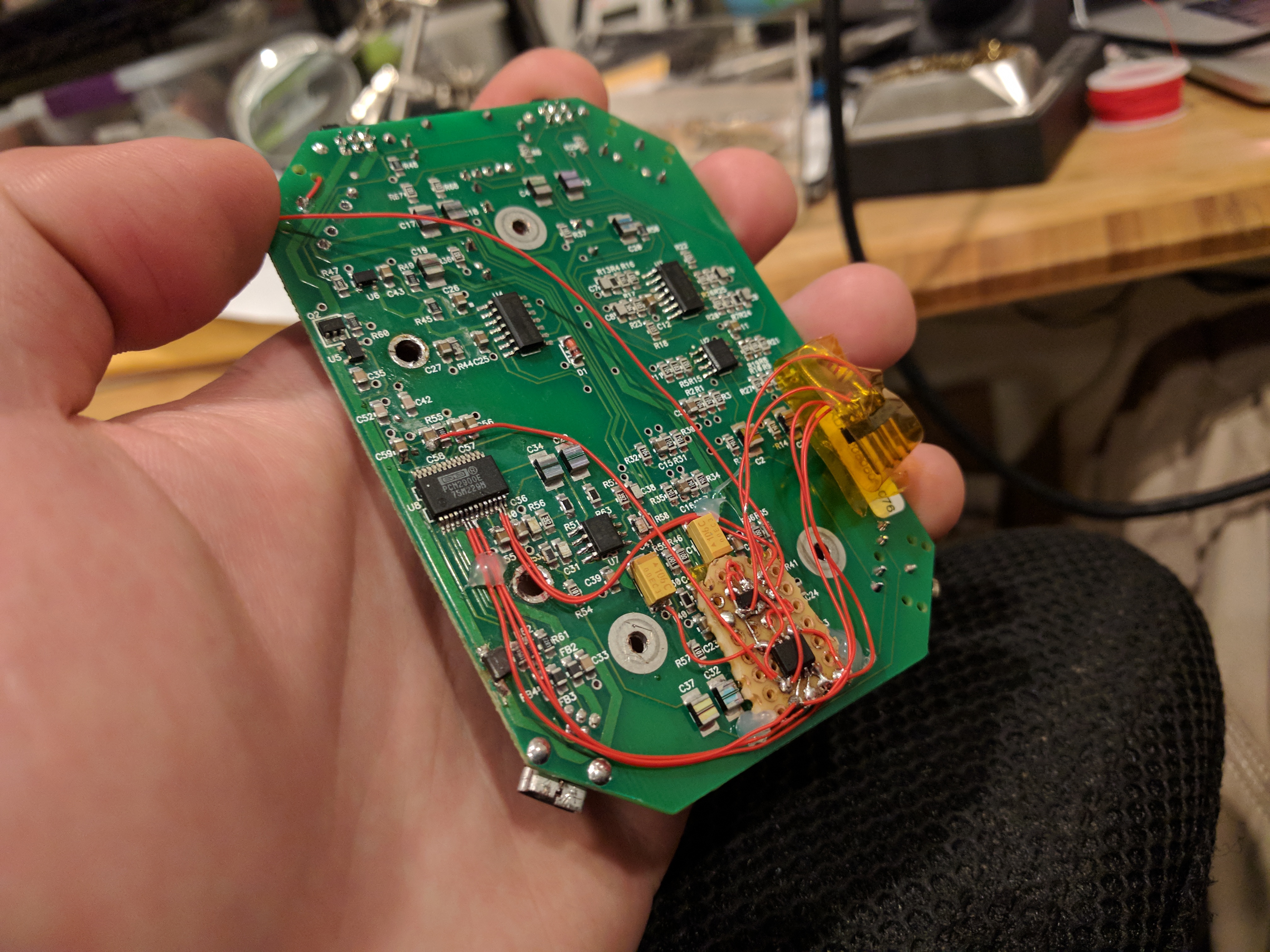
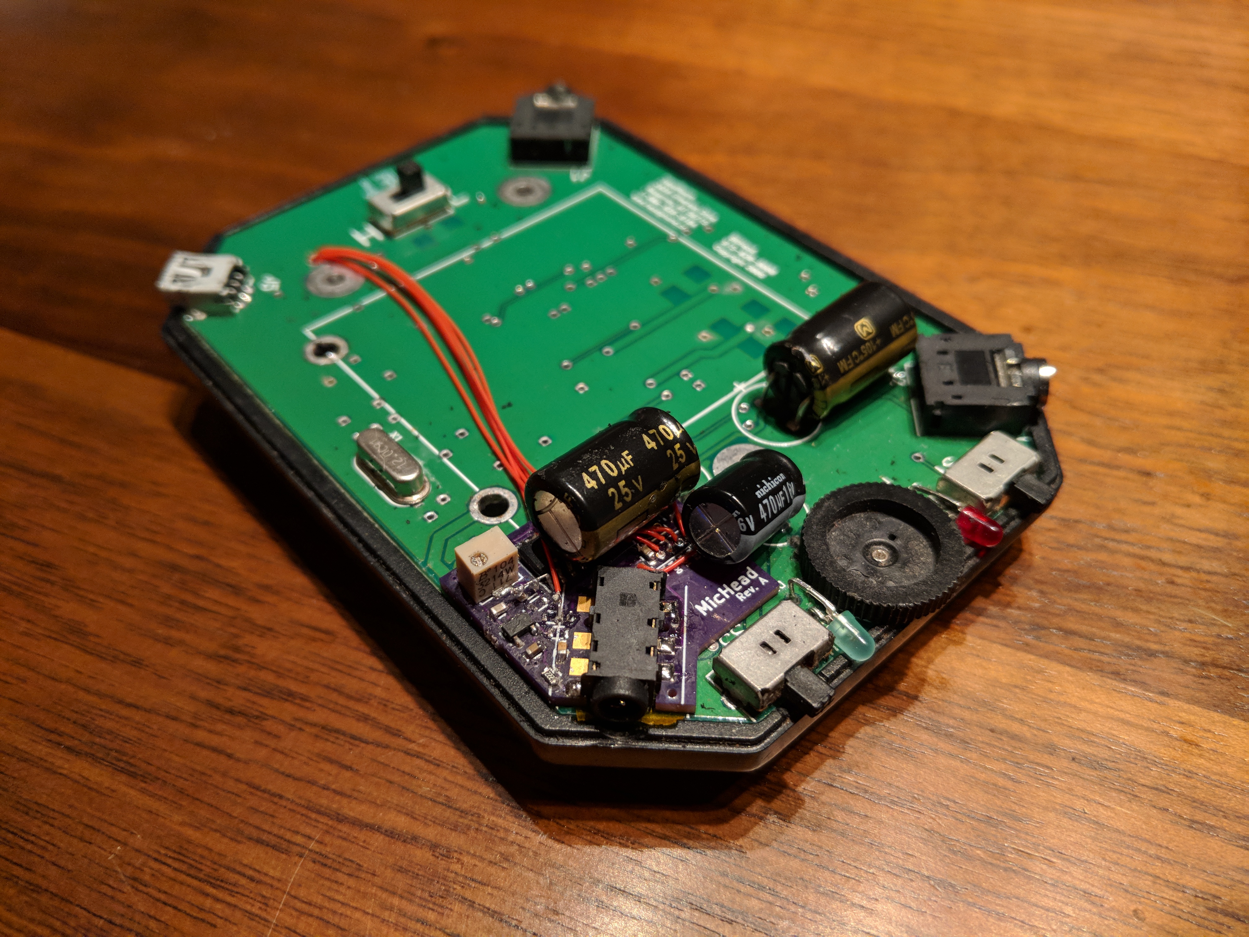
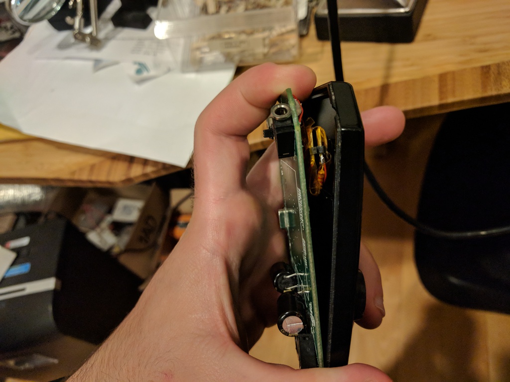
I tore the thing apart again to come up with a plan of attack. Apparently, the BitHead is based on a TI PCM2900 USB codec chip -- and, to my surprise, not only does the chip have a line-in pin, but it also has three HID-keyboard pins! I was in luck: I'd be able to use not just the microphone, but also the little buttons that go with it.
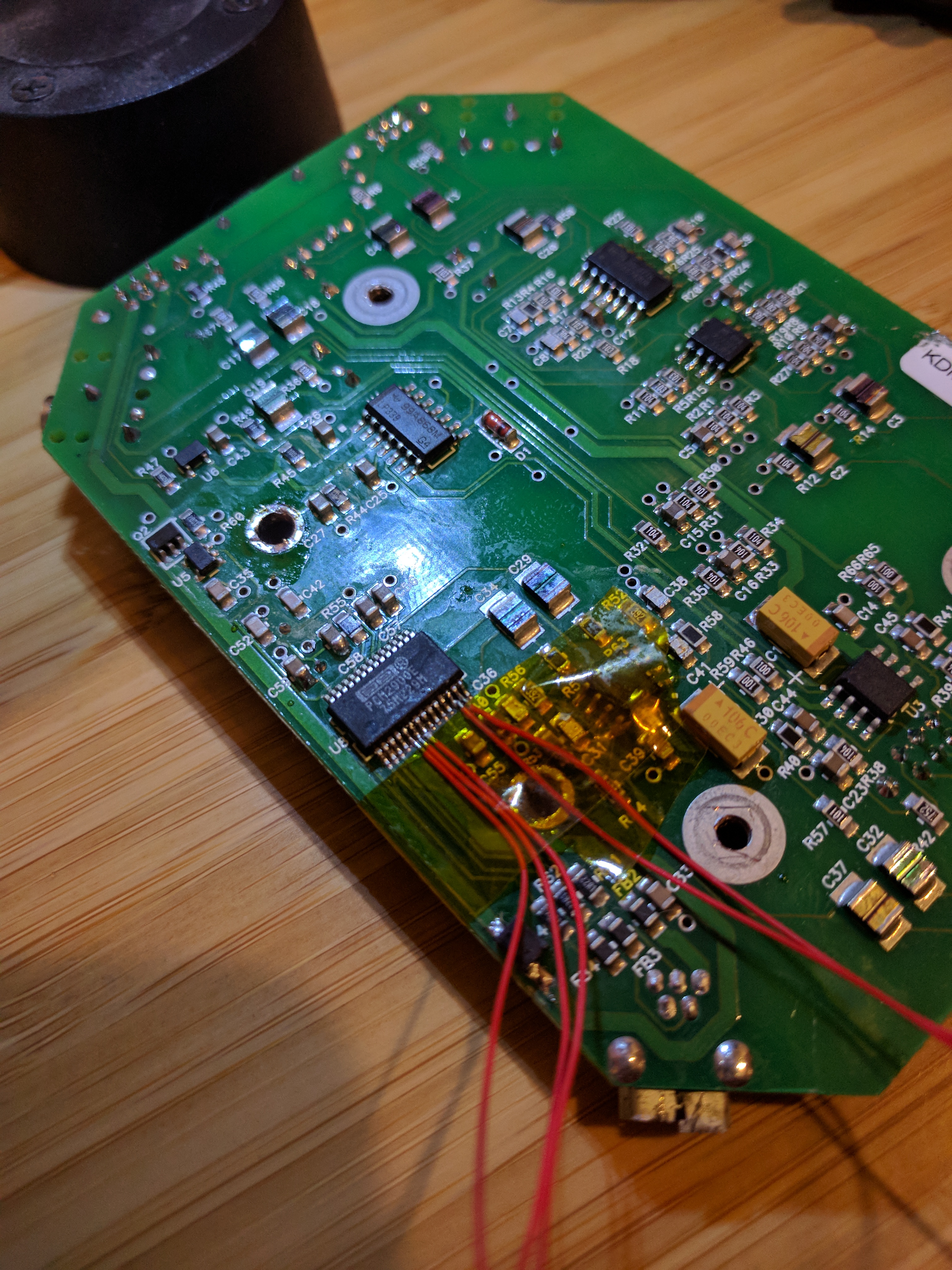
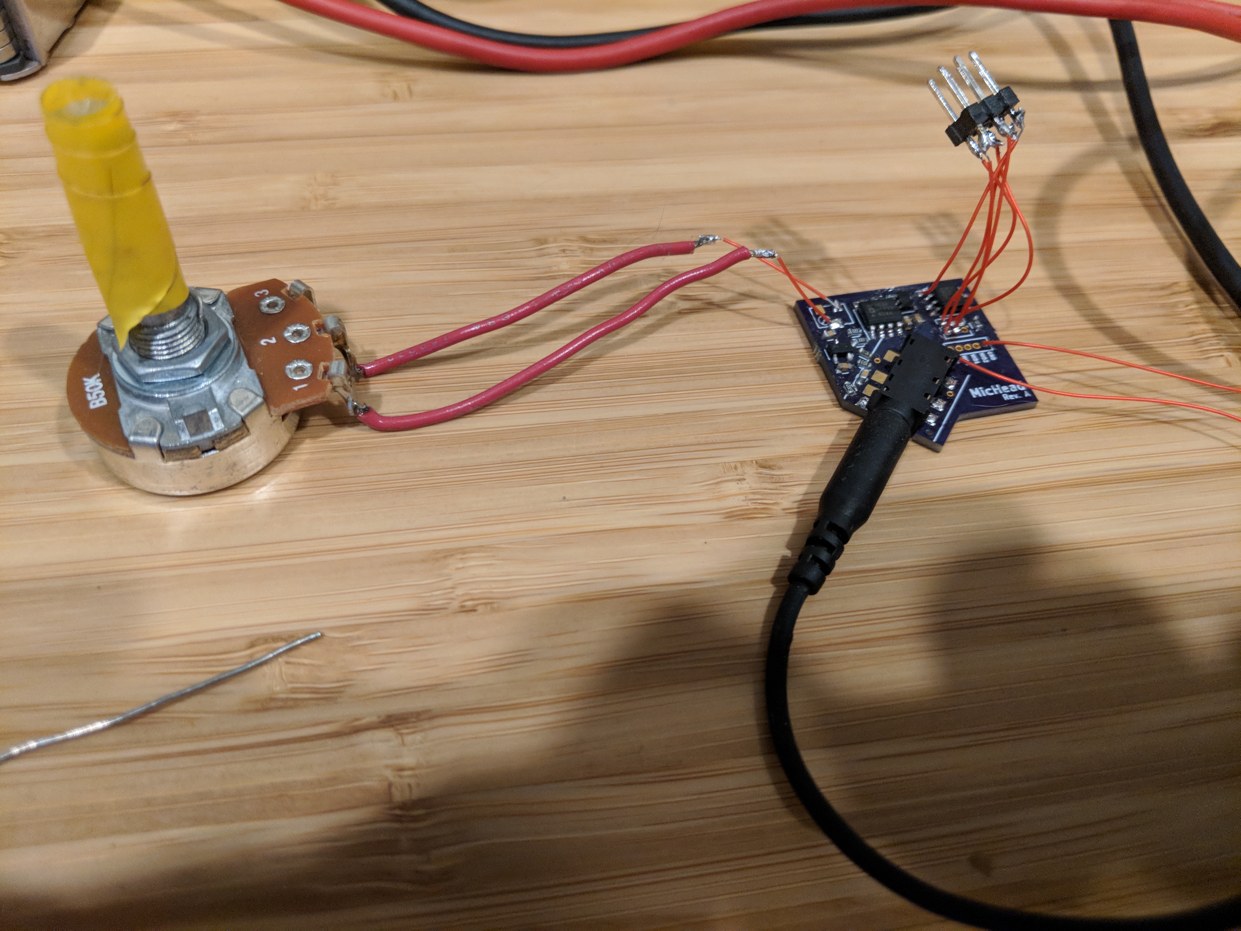
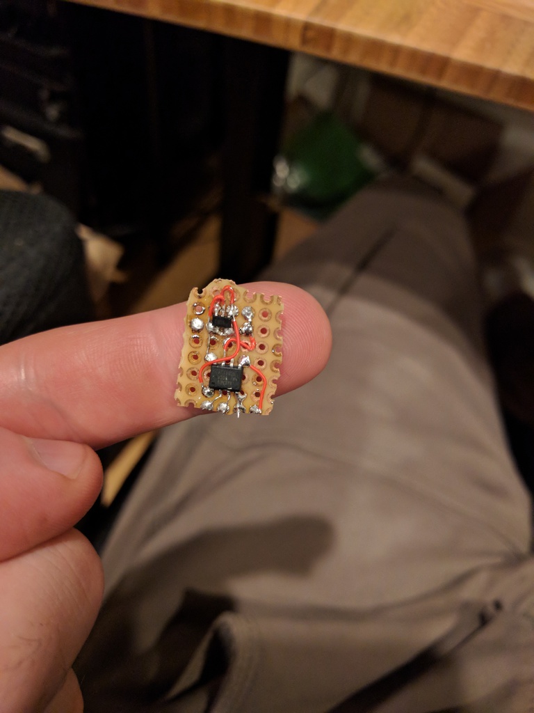
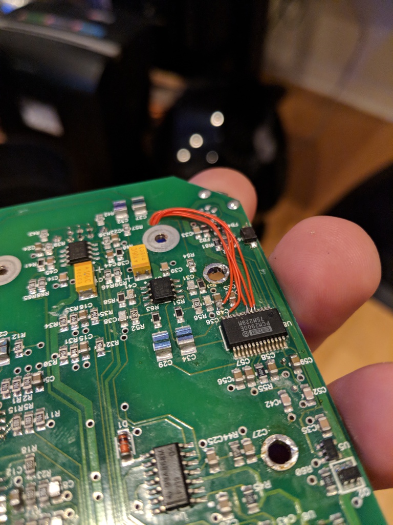
All I needed to do was to build a circuit to bias the microphone (microphones want to be powered in a very specific fashion), and to build a circuit to detect the specific resistance values that the headset would present for each button press. So off I went to DigiKey, and ordered a handful of parts: a few resistors and capacitors to make the bias network, and a microcontroller (specifically, an ATtiny102) to read the resistance values from the buttons and convert them to digital signals to send to the codec chip. In the mean time, a little bit of time soldering got me the pins I wanted on the part, and my new 4-pin headphones jack soldered down on the edge of the board:

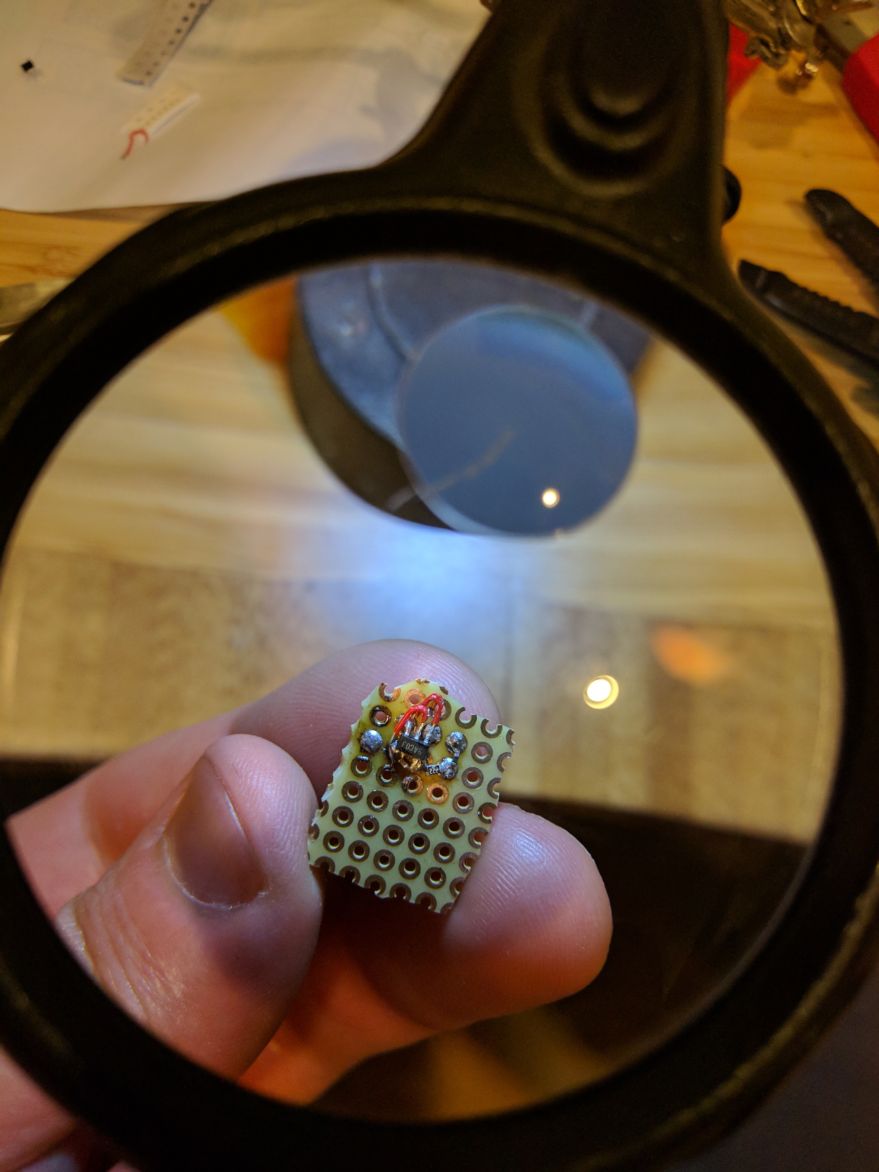


And so went the first iteration of it. There were a few problems with the first version, though: for one, it didn't really fit in the original case. And for another, the microphone was way too quiet: apparently the PCM2900 chip takes a "line-level" input, and the microphone is quite a lot below that. And, if I turned the gain up in software, there was an infernal whining sound; apparently, the microphone signal had some sort of noise coupled onto it from wherever I was drawing my power (which made sense, since I didn't use any decoupling capacitors to speak of).
I was going to need some analog gain -- an amplifier of some sort. And, clearly, this meant that I'd have to do it again, because there was no way I was going to solder an op-amp circuit onto that piece of perfboard. I was left with only one option: I was going to have to make a board for this.
Back when I was in high school, and even a good chunk of college, fabbing out a PCB was prohibitively expensive. For one, my project budget was basically nothing, but for another, PCBs were just plain and simple way more expensive back then! I remember prototype PCB runs being on the order of $250 for a few PCBs -- and that's if they're obvious rectangular PCBs that have nothing fancy about them, and if you were okay with them taking a month or so. So whenever I had cause to do a board back then, I'd do it at home, in my basement, with laser printer toner transfer to make an etch resist, and all manner of noxious chemicals to do the etching; and the quality always sucked, so I never designed with particularly small components.
These days, PCBs are dirt cheap, and fast. OSHPark prices entirely by size, with no minimum setup charge, at an insanely low $5 per square inch -- and for that, you get three copies of a two-layer board with solder mask and silk screen on both sides. If you want to go even cheaper than that, Seeed Studios will do a 15-in^2 board and give you 10 of them, all for $4.90, if you're willing to wait for it to arrive from China! PCB design software has come a long way, too -- the terrible user experience that EAGLE had to offer that you had to pay $100+ for a license for can now be had as open source software, too.
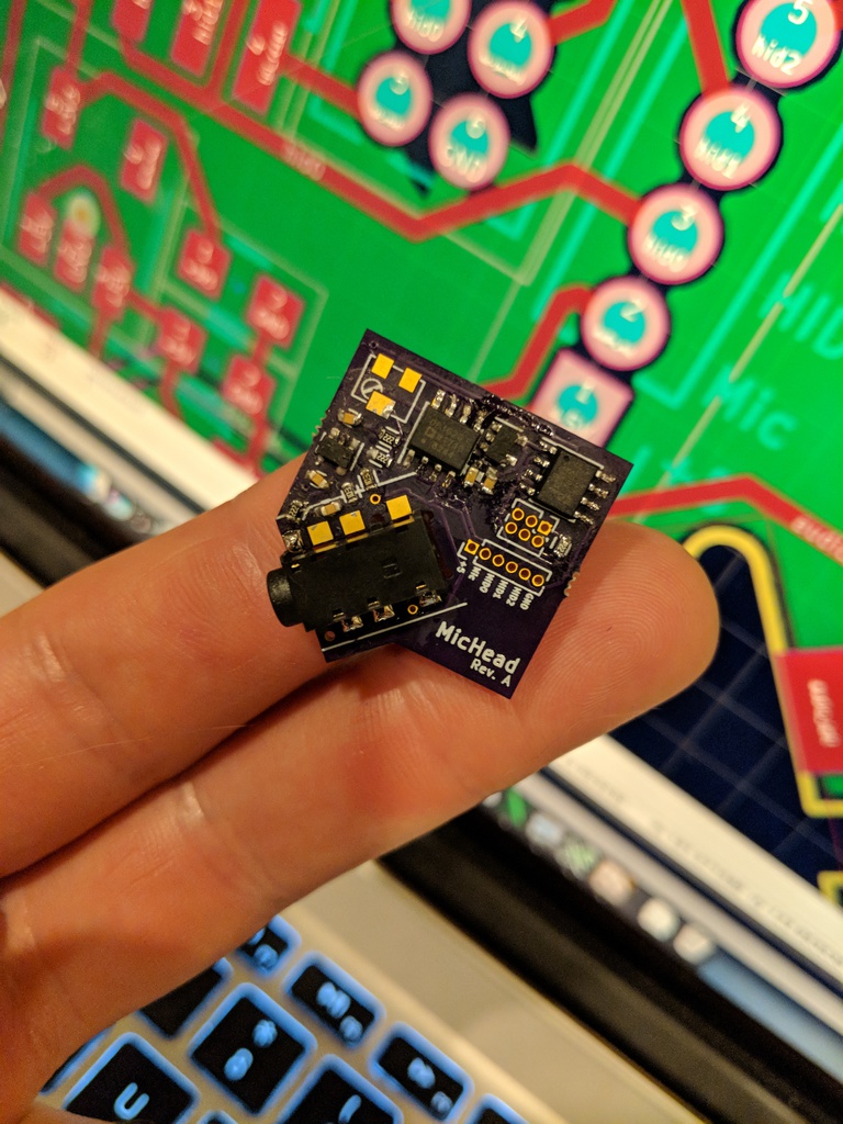
So, armed with all of these modern advancements in hobbyist electronics, I truly had no choice: I was going to make a board.
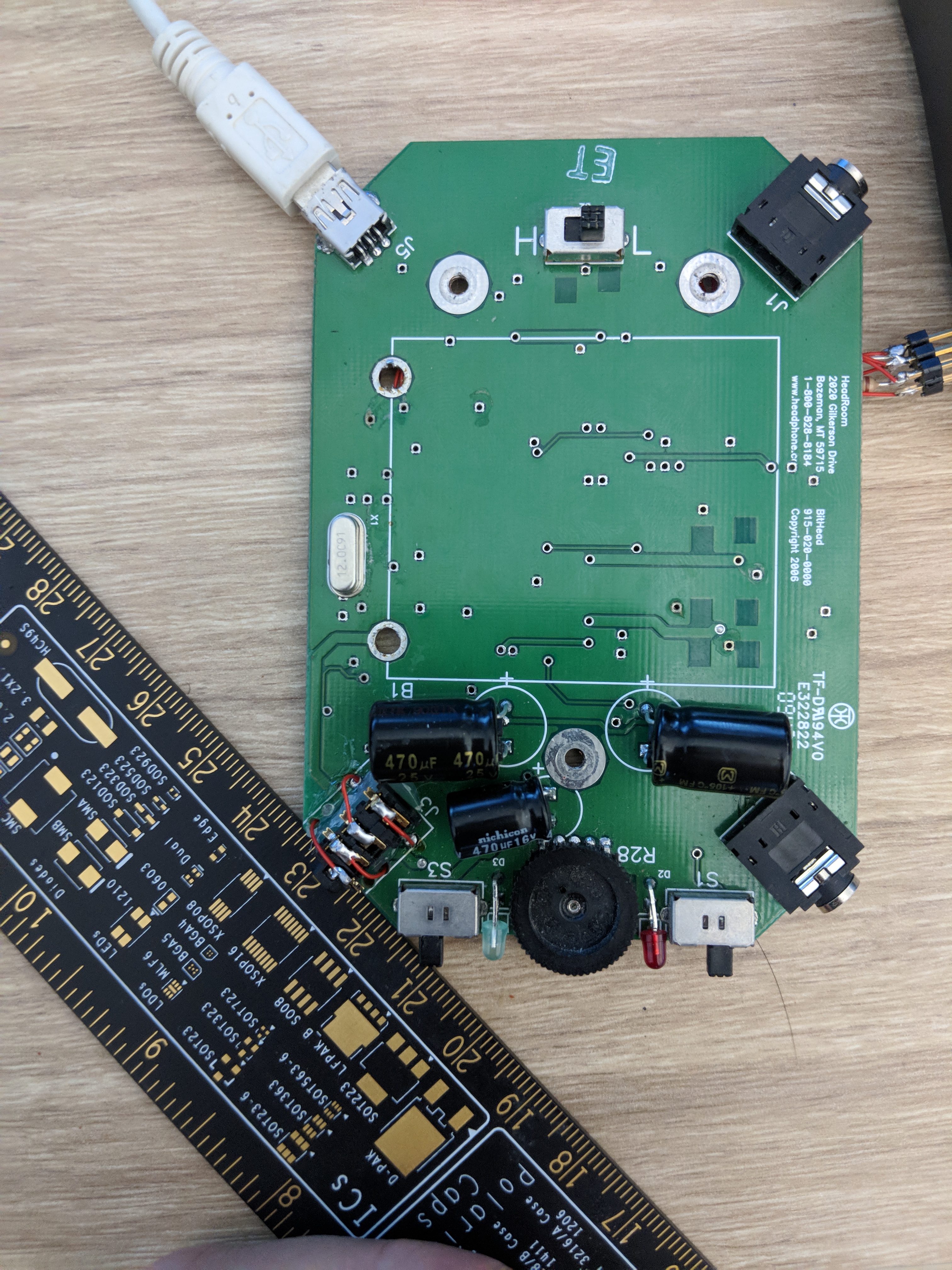
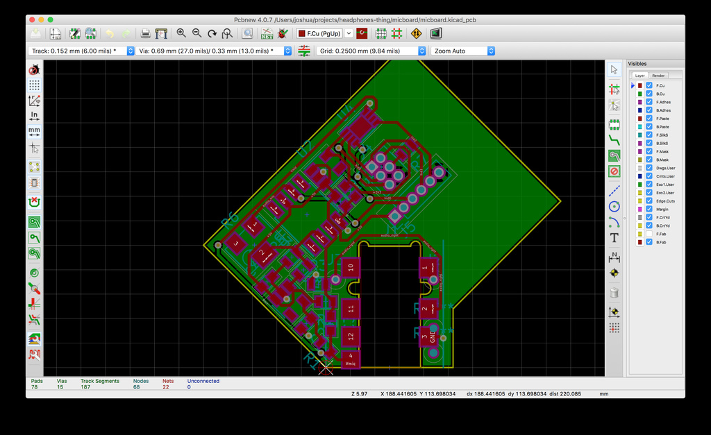
The first step in this affair was to take some measurements. I knew that I wanted my new board to sit down where the old headphones jack lived -- basically, I wanted it to be a 'headphones jack on steroids', that was (almost) a drop-in replacement for the old one. For bonus points, the headphones jacks that I chose for the first attempt happened to be flush-mounted -- that is to say, they occupied some of the same vertical space as the PCB, so it really would sit down exactly like the original! I took out my trusty NVIDIA ruler and took some photos of the board to scale, and started making measurements in Photoshop of the dimensions I'd need.

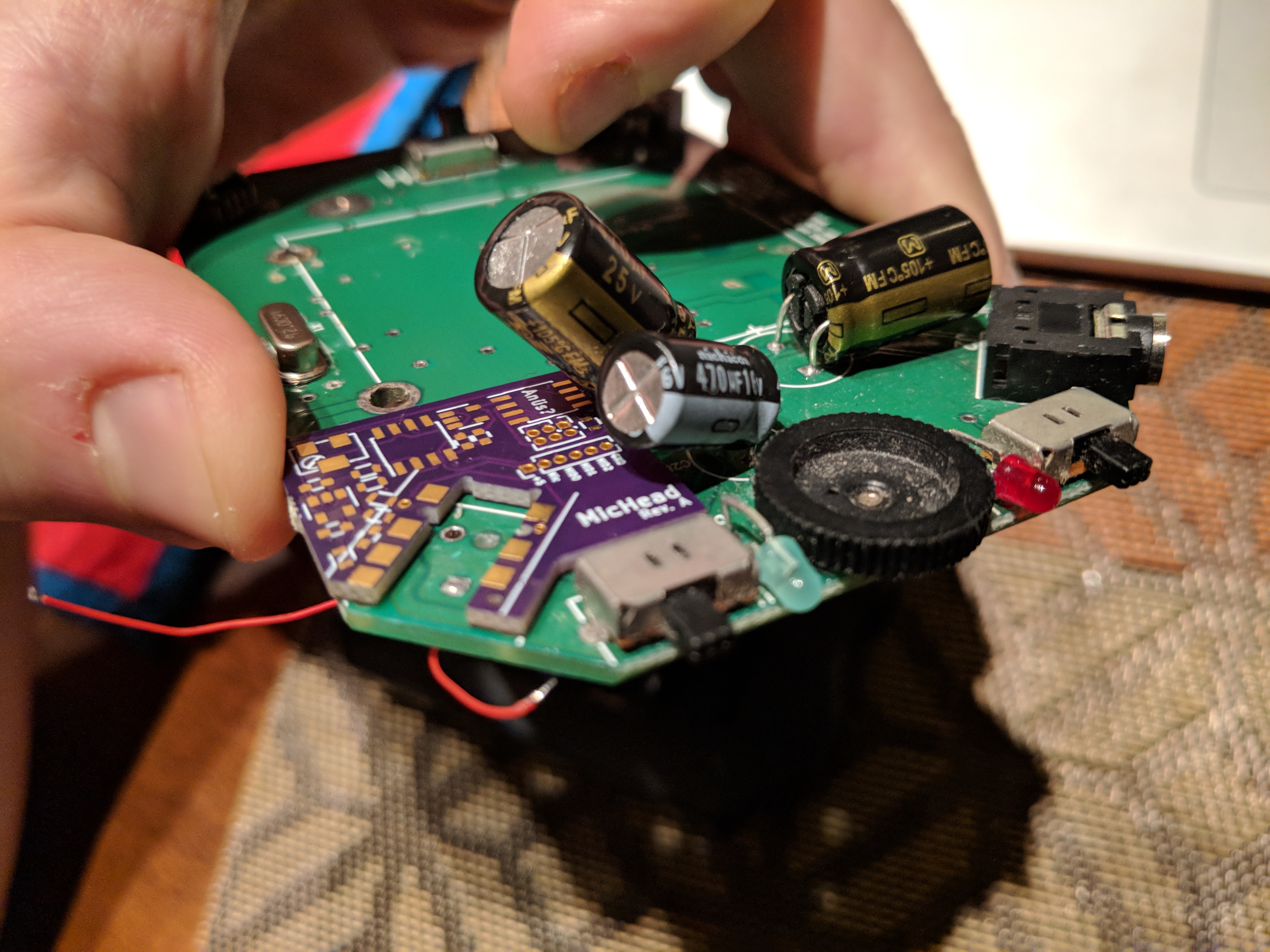

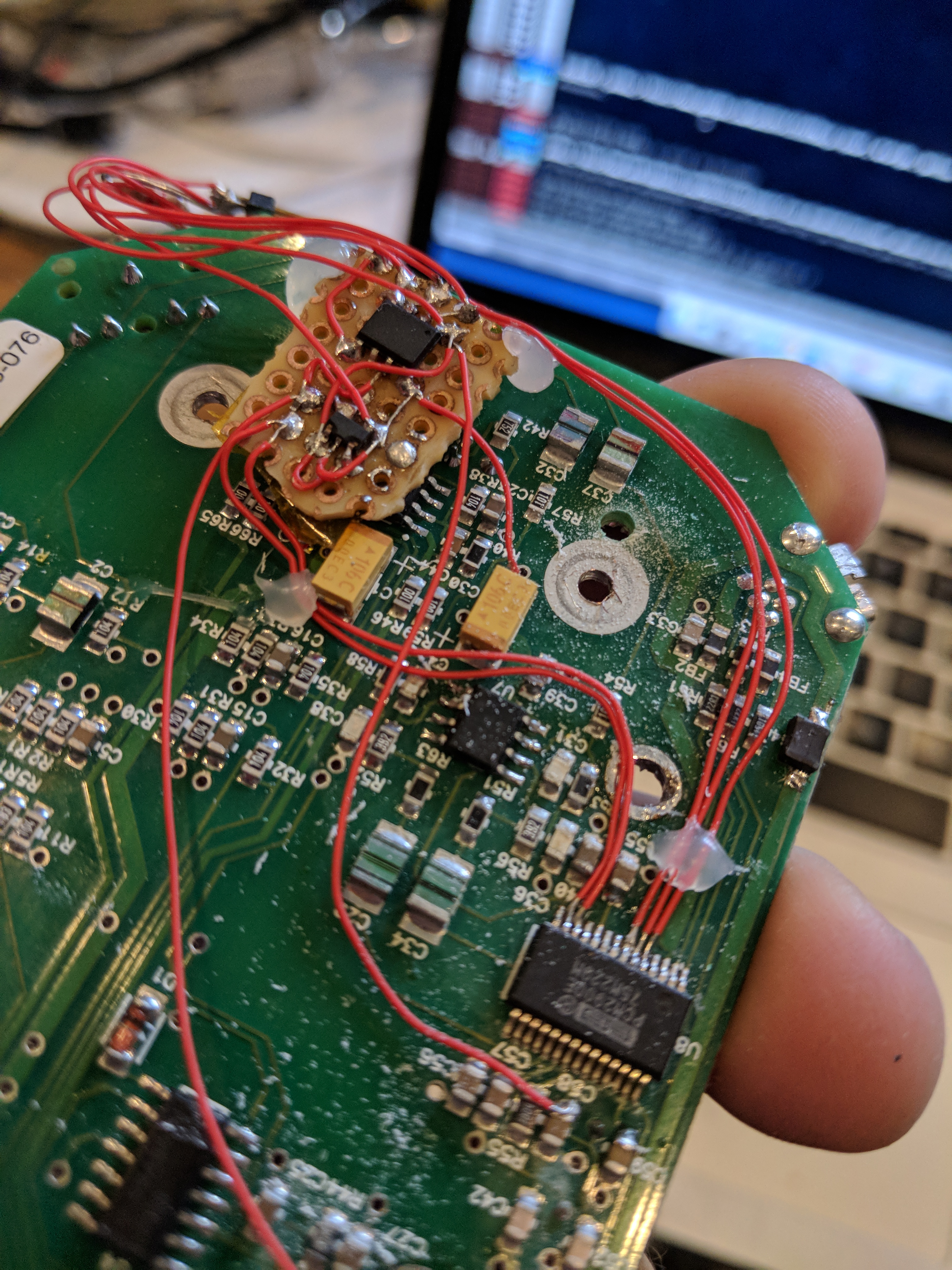
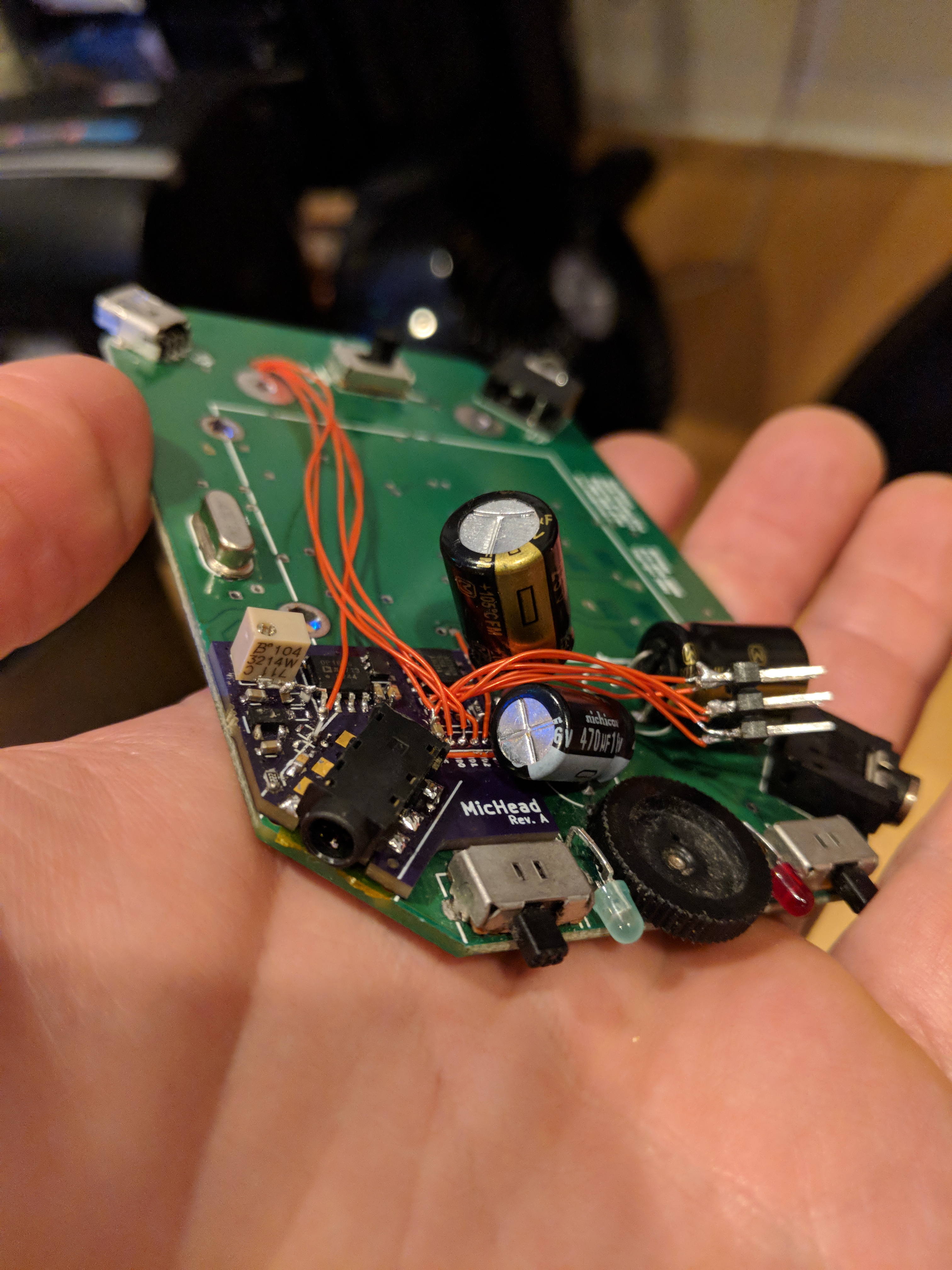

It wasn't all perfect. The op-amp circuit I designed was, to put it lightly, full of crap. It picked up noise from basically everywhere. I came up with a rework to redesign it and fix it up, involving standing three components on their ends, and soldering to the other ends. (You can zoom in on the above, if you're so inclined to see it. And, thanks to kevtris on this one, who stared at my schematic and figured out what I did wrong in an instant, after I spent hours beating my head!) But after that fix, it worked! Microphone sound quality is not as audiophile-grade as the rest of the system, but it's certainly good enough for audioconferencing -- and, anyway, the MEMS microphones in these headsets are pretty miserable. I'm pretty proud of how it came out; visually, it doesn't offend more than it has to, and the results are as good as I could have hoped for.
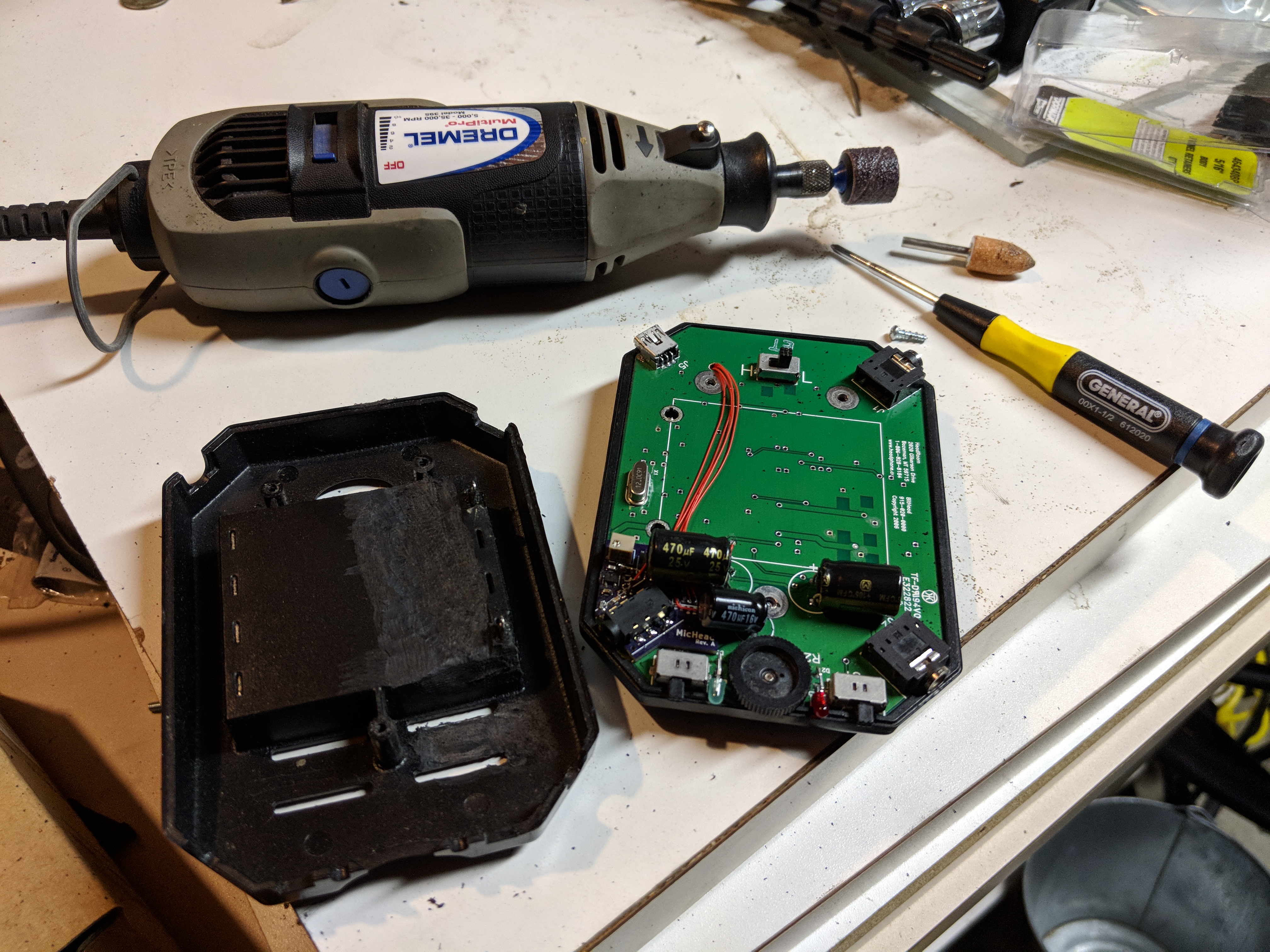
From then, the only thing remaining was to fit it into its case. The extra components increased the Z-height of the unit just enough that it barely didn't fit into its enclosure. In the car-modding community, there exists this wonderful euphemism, "clearancing", which roughly means "to beat the snot out of with a sledgehammer until it fits"; in this case, I used a Dremel to "clearance" the some of the plastic away in the upper case. Finally, I reassembled it all -- and it all still works!
And that, I suppose, is the story of how I spent $107 in parts (including spares and duplicates...) and what must have been 40 or so hours of engineering time to add a microphone input to a headphones amp that cost about $150... seven years ago. I was going to say that it surely couldn't have been worth it, given how much the price of such things has dropped in the interim ... but as it turns out, nothing on the market has this feature! And anyway, the crossfeed circuit on the BitHead is really good, and giving it up would be a shame.
And anyway anyway, the most important thing is that this was cooler.
Joshua Wise, 2017
"It works!"